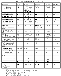
 [Click Here to See Table]
This page is a brief summary of PL Technical Report PL-TR-94-2187, "Users' Guide for the Topside Ionospheric Plasma Monitor (SSIES, SSIES-2 and SSIES-3) on Spacecraft of the Defense Meteorological Satellite Program (DMSP), Vol. 1: Technical Description." This report is available by request from K. Martin.
The Topside Ionospheric Plasma Monitor (acronym SSIES) measures the thermal plasma at the location of the DMSP spacecraft. The SSIES sensors are tailored to the anticipated environment at 840 km altitude and at all latitudes, all local times, all seasons and all phases of the sunspot cycle. Typically this environment is composed of three ion species; hydrogen (H+), helium (He+) and oxygen (O+). At mid-latitudes, the nighttime ion temperatures are approx.1000 deg K ( 0.086 eV ) and daytime ion temperatures are of the order of 3000 deg K (0.26 eV). Nighttime electron temperatures are approx. 1200 deg K (0.10 eV) and daytime electron temperatures are approx. 3500 deg K ( 0.30 eV ). These temperatures increase and decrease with solar activity. In the regions of strong energy transport from the magnetosphere to the ionosphere, the ion and electron temperatures increase and are spatially structured. For an ion temperature of 2000 deg K, O+, He+ and H+ have thermal velocities of 1.4 km/s, 2.9 km/s, and 5.7 km/s, respectively. At 2000 deg K, the electron thermal velocity is 240 km/s. Plasma densities usually are between 10^3 and 10^6 cm^(-3). The electron thermal motion is much faster than the ion thermal motion because thermal motion scales as the inverse of the square root of a particle's mass.
Table of All the Geophysical Parameters Measure and Their Sampling Rates
The SSIES, SSIES2 and SSIES3 systems contain the following sensors:
The SSIES3 also contains a plasma plate on the ion array for measuring the ionospheric electrons. In addition to the sensors for collecting environmental data, the SSIES/SSIES2/SSIES3 systems (except for F9) contain a sensor for measuring the electric potential between the plasma and the spacecraft. This sensor and its electronics are know as SENPOT. The sensor part of SENPOT is a section of the ion sensor aperture plane which is electrically isolated from the spacecraft by 100 Mohms. The Main Electronics Package (MEP) and the electronics package for the DM and SM sensors (DSM) are located inside the spacecraft.
External view of the ions sensors with the aperture array and the electron sensor on the end of its boom.
All of the ion sensors are planar, electrostatic analyzers, often referred to as Faraday cups. The aperture of the incoming particles is a plane. The ions pass through a series of flat screens that have applied electrostatic potentials. The ions are ten collected on a flat metal plate. The current to the plate is detected and reported as telemetry data. The planar geometry is appropriate for measuring thermal ions since the spacecraft speed is supersonic with respect to the ions. For the electrons, the spacecraft speed is subsonic and a spherical geometry is more appropriate for collecting and measuring them. The spherical electron sensor, often referred to as a Langmuir probe, is separated from the spacecraft by a short boom because the Sun creates an envelop of low energy electrons within a few centimeters (a Debye length or two) of the spacecraft surface.
The values for ion drift (which is the most widely disseminated data ) are with respect to coordinates defined by the ion drift meter and the RPA, not by the spacecraft. The spacecraft coordinates are +X radially down, +Z is parallel to the solar panel boom when deployed and +Y completes the right- handed system. When the ascending node is in the morning sector, the spacecraft's +Y side is facing the ram (the direction of spacecraft motion) and the ion sensor array is mounted on the +Y side as shown in Figure of the SSIES/SSIES2 sensors mounted on the DMSP spacecraft.
When the ascending node is in the afternoon / evening sector, the spacecraft's -Y side is facing the ram and the ions sensor array is mounted on the -Y side. Bulk ion flow anti-parallel to the spacecraft velocity increases the apparent ram velocity into the RPA sensor and defines the positive direction for the RPA's determination of the drift. For the driftmeter, the positive vertical flow is toward the spacecraft's -X axis (upward). The horizontal flow is toward the -Y spacecraft axis for morning ascending node and toward the +Y spacecraft axis for afternoon/evening ascending node. The attached figure shows the relationship between the driftmeter's positive flow direction to the spacecraft and geographic directions.
Go to DMSP Home Page