The SSM Instrument for DMSP F12 and Beyond
The SSM is a triaxial fluxgate magnetometer system used as a space
environment sensor for the Defense Meteorological Satellite Program (DMSP)
spacecrafts 12 through 20. This instrument was designed and built at
NASA/Goddard Spaceflight Center under the direction of Dr. Mario Acuña.
The first of this series of magnetometers was placed in low Earth orbit in
September 1994. A "proof-of-concept" SSM instrument was built from
surplus magnetometers by Johns Hopkins Univ./Applied Physics Lab. and flown on
the DMSP F7 spacecraft from Dec 1983 to late 1987.
The parameters measured by the SSM are the three components of the magnetic
field vector. The SSM magnetometer takes and reports 12 readings per second
for the Y and Z axes. Only 10 readings of the 12 readings per second are
reported for the X axis due to telemetry limitations. (The SSM's axes are
aligned with the spacecraft's axes where X is downward and aligned to local
vertical within 0.01 degree, Y is parallel to the velocity vector for
spacecraft with ascending node in the afternoon/evening sector, and Z is away
from the solar panel and anti-parallel to the orbit normal vector.) The range
is from +65535 to -65535 nT for each axis, with a one-bit resolution of 2 nT,
(1 nT=1.0E-5 gauss=1.0E-9 Tesla).
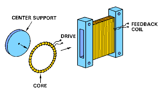
The fluxgate sensors are constructed utilizing the ring core geometry. The drawing shows the construction of one of the
three identical sensors. Important elements in the design of the sensor are
the feedback coil which nulls the ambient field within +/- 2000 nT, and the
sensor core itself since they can be shown to be the most significant sources
of error, both from the alignment stability point of view, as well as
temperature stability.
Here individual axis nulling is utilized, that is, each axis is nulled
independently in only one direction. This is the most common approach but
suffers from extreme sensitivity to cross-fields since the ambient field is
nulled only along the sensor axis. Thus any distortion or motion of the sensor
core within the feedback coil represents an effective change due to the
presence of the transverse field.
A rigid attachment of the sensor core to the feedback coil usually results
in differential expansion stresses being transmitted to the sensor core which
can produce significant alignment shifts, zero level changes as well as
dramatic increases in sensor noise levels. These problems have been solved by
carefully matching the thermal expansion coefficients of the elements involved
(core, windings, support structure) to minimize differential stresses and
changes in the relative geometry between the core and the feedback coil.
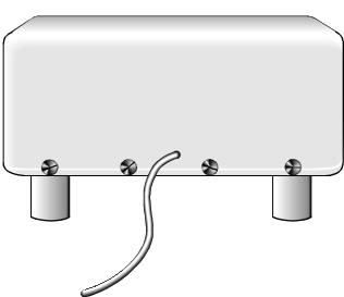
The three sensor elements are mounted in three orthogonal directions in a
rigid frame which is covered with a fiber glass shell. This assembly is
attached to the mounting plate by four plastic legs. The legs provide
electrical and thermal isolation from the spacecraft's frame.
 The mounting plate is aligned with the spacecraft's
axes with an accuracy of 0.5 degree/axis. Post-flight calibration can
determine this "mis-alignment" between the SSM's axes and the
spacecraft's axes to an accuracy of 0.1 degree/axis or better.
The complete SSM instrument consist of: (1) The sensor assembly with cable,
(2) the electronics box, and (3) the regulator box for the heater on the
sensor assembly. The sensor assembly is 112 by 90 by 67 mm and weighs 290 g
with cable.
The SSM sensor was designed to be mounted on the exterior of the Earth
facing panel of the Equipment/Service Module (ESM). That was found to be an
inappropriate location for the sensor and it was moved to the truss which
connects the ESM to the apogee-kick motor (AKM or 3rd stage rocket). In this
move the sensor was rotated 180 deg about the Z axis. By changing the sign of
the counts-to-field constants, the output of the sensor is still reported as 3
vectors aligned with the spacecraft axes. The SSM sensor is mounted on the
truss structure only for F12, F13 and F14. For F15 to F20, the sensor will be
placed at the end of a 5 meter Astromast boom which is deployed radially
upward from the truss assembly. This will greatly decrease the magnetic fields
from the spacecraft which are observed by the sensor.
updated: 30 May 1996
Please read this Data Usage Notice
Go to DMSP Home Page
 The drawing shows the construction of one of the
three identical sensors. Important elements in the design of the sensor are
the feedback coil which nulls the ambient field within +/- 2000 nT, and the
sensor core itself since they can be shown to be the most significant sources
of error, both from the alignment stability point of view, as well as
temperature stability.
  The mounting plate is aligned with the spacecraft's
axes with an accuracy of 0.5 degree/axis. Post-flight calibration can
determine this "mis-alignment" between the SSM's axes and the
spacecraft's axes to an accuracy of 0.1 degree/axis or better.